Prompted by a suggestion from Tim Jackson I have investigated the partial frequencies of tubular bells and in particular, which partial or partials determine their strike pitch – the note that we hear.
This paper was updated on 14/1/2023 with measurements for the small tubes at Caterham Valley.
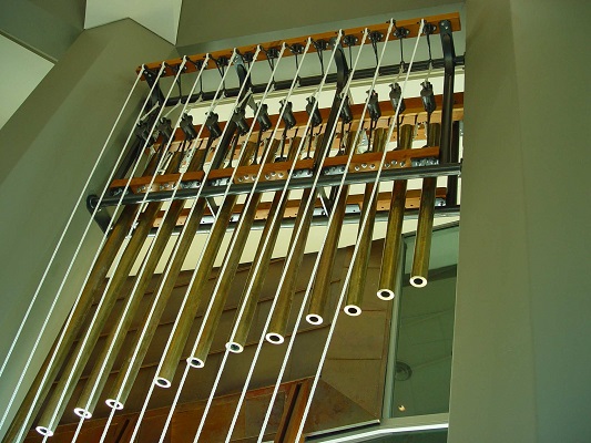
Tubular bells were patented for use in churches by John Harrington of Earlsdon near Coventry in 1884 and were produced by Harrington, Latham & Co and successor firms until the 1920s. Chris Pickford in an article in The Ringing World issue 5787 (25 March 2022) pages 263-4 gives a description of the tubular bells at St Luke, Ironbridge, including photographs of the bells and chiming frame. The Whiting Society website has a description and photographs of the installation at Riddings, Derbyshire. Here is a recording of the bells at Riddings. A paper presented to the International Congress on Acoustics in Sydney in 2010 investigates the acoustics of 13 tubular bells in detail, including their strike pitch (ref 1). Here is a picture of 12 of the tubes used in that study:
Tubular bells have a characteristic ‘twangy’ sound due to inharmonic partials, and it can sometimes be quite hard to decide the pitch or note that they sound. The reasons for both will be explained below.
To summarise the investigation, it is shown that the strike pitch of Harrington tubular bells is determined by the fourth partial, numbering from the lowest. The strike pitch is a virtual pitch generated in our auditory system by the fourth, fifth and sixth partials, and is an octave below the fourth partial. This is different from bells of conventional shape, for which the strike pitch is determined by the fifth partial – the nominal. The lowest two partials in tubular bells are very quiet, especially the lowest, and in practice care must be taken to ensure the right partial is selected when determining the note of a tubular bell.
A recent experiment demonstrates the physical vibration patterns in a tubular bell.
For those who want to skip the detail below, a recipe is given in the last section of this paper on how to measure the nominals and note-names of a set of tubes.
Sets of tubular bells investigated
This investigation included the following sets of tubular bells:
| Location | No. of tubes | Founder | Date | Recordings |
|---|---|---|---|---|
| Baconsthorpe, Norfolk | 8 | Harrington | 1892 | Chris Richmond |
| Carnforth, Lancashire | 8 | Harrington | 1908 | Youtube / niche2000 |
| Caterham, Surrey | 8 | Harrington | 1891 | Taken by me |
| Caterham Valley, Surrey | 8 | Unknown (small tubes) | 1978 | Taken by me |
| Daylesford, Gloucestershire | 10, but 3 stolen | Harrington | 1893 | Chris Pickford |
| Droitwich, Worcestershire | 8 | Harrington | 1902 | Chris Pickford |
| Dunedin, New Zealand | 10 analysed of 13 | Harrington | 1906 | Laurie Alexander |
| Effingham, Surrey | 8 | Unknown (iron tubes) | 1913 | Taken by me |
| Finsthwaite, Cumbria | 10 | Harrington | 1892 | Youtube / Mark Bellhangman |
| Haywards Heath, Sussex | 10 | Harrington | 1888 | Richard Hutchings |
| Icomb, Gloucestershire | 8 | Harrington | 1902 | Chris Pickford |
| Ironbridge, Shropshire | 8 | Harrington | 1920 | Chris Pickford |
| Lindfield, NSW, Australia, St David’s Methodist Church | 8 analysed of 13 | Danks | 1936 | Laurie Alexander |
| Longstowe, Cambridgeshire | 8 | Harrington | 1898/1903 | Laurie Alexander |
| Maentwrog, Gwynedd | 8 | Harrington | circa 1896 | Huw Jenkins |
| Mappleborough Green, Warwickshire | 8 | Harrington | 1888 | Chris Pickford |
| Milford, Surrey | 8 | unknown | unknown | Taken by me |
| Nelson, New Zealand | 8 | Harrington | 1889 | Laurie Alexander |
| Nelson, New Zealand | 8 | Harrington | 1889 | Laurie Alexander |
| Parwich, Derbyshire | 8 | Harrington | 1919 | Taken by me |
| Perth, Australia, Swan Tower | 12 | Harrington | 1896 / 1911 | Conference paper |
| Perth, University of Western Australia | 1 | Harrington | Unknown | Conference paper |
| Riddings, Derbyshire | 10 | Harrington | circa 1900 | Youtube / 8spliced |
| Rownhams, Hampshire | 8 | Harrington | 1889 | Tim Jackson |
| South Holmwood, Surrey | 8 | Harrington | circa 1903 | Taken by me |
| Sydney, Australia, Darlinghurst | 13 | Harrington | 1889 | Laurie Alexander |
| Sydney, Australia, St Andrew, Summer Hill | 8 | Harrington | 1907 | Laurie Alexander |
| West Anstey, Devon | 8 | Harrington | 1886 | Ringer Mikey |
| West Ewell, Surrey | 8 | Harrington | 1894 | Taken by me |
The tubes at Effingham are an excellent match to the Harrington bronze tubes even though they are made of iron by an unknown manufacturer. The tubes at Caterham Valley (a demo set on the belfry wall, like doorchimes) also match the models below well even though they are much smaller and thinner than Harrington tubes.
The investigation into each set involved, first, estimating the strike pitch of each tube by listening to the recording and adjusting a reference tone to sound the same note. The reference tone was generated using my pitcher program. This is the only way to measure the pitch that we hear, as it is not present in the sound, but generated in our auditory system. The pitches were not always easy to estimate because in some of the recordings the tubes are rung in quick sequence, and sometimes the overall impression of of a tube was of a confused set of partials rather than a single note. As all the tubes in each set were designed to sound a musical scale, the sound of adjacent tubes was sometimes used to help determine the pitch. The pitch of the tubes described in the conference paper was measured using similar techniques, and the researchers had similar problems establishing the pitch of some tubes.
Once the pitch of each tube had been estimated, the partials were measured. This was done after pitch estimation to prevent knowledge of the individual partial frequencies biasing the estimation of pitch. One point of caution – it proved quite difficult to see the lowest partial for some tubes because it is very quiet.
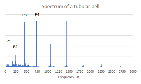
Here is the spectrum of a tubular bell (tube 6 from Mappleborough Green) with the lowest four partials named.
Partial frequencies of tubular bells
The partials of all the tubes followed the same pattern. As described in the Physics of Musical Instruments (ref 2) pp 95-96 and 641-642, the theory of vibrating metal tubes suggests that the frequency fn of partial n (counting from 1 as the lowest) is
fn = K * ( √(a2 + b2) / L2 ) * (2n + c)p
where K is a constant depending on the elastic properties of the metal, a is the external radius, b is the internal radius and L is the length of the tube. p, the power to which (2n + c) is raised, is given as 2 in the text books and c is given as 1. These values do not come from an analytical model but from numerical solution of the equations of vibration. As will be seen below, different values give a better fit for the tubes studied here.
Here are the partial frequencies of the 8 tubes at Icomb plotted against (2n + 1)2:
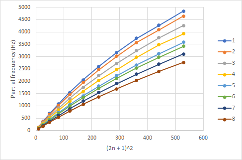
The actual frequencies of partials with higher n for all the tubes are lower than the model predicts.
To further investigate the partial frequencies, it is convenient to normalise them. Because it is often not possible to measure the lowest one or two partials for a tube, and because it will become clear that partial n=4 determines the pitch of the tube, the frequencies of all the partials can be normalised by dividing them by the frequency of partial 4.
The resulting equation derived from the model is:
fn / f4 = (2n +c)p / (2 * 4 + c)p, or taking logs:
log (fn / f4) = p * log { (2n +c) / (8 + c) }
This removes any dependency in the model on the dimensions of the tubes or the metal from which they are made. A least-squares regression of up to 14 partials in the 233 tubes gives values p = 1.651 and c = 0.287. A plot of log (fn / f4) against log { (2n +c) / (8 + c) } for all the measured partials appears as follows:
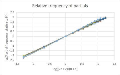
There is clearly a great deal of consistency in the partials across all the tubes, whose pitches span 1.9 octaves. The tubes include ones made of iron and possibly, brass, and very small tubes like doorchimes. This result shows a good fit of tubular bell partials to the modified Chladni law, as further explored in work I have just completed on hemispherical bells.
The average cents for each partial relative to partial P4 across all 233 tubes is follows:
| P1 | P2 | P3 | P4 | P5 | P6 | P7 | P8 | P9 | P10 | P11 | P12 |
|---|---|---|---|---|---|---|---|---|---|---|---|
| -3668 | -1941 | -816 | 0 | 631 | 1139 | 1562 | 1926 | 2242 | 2530 | 2796 | 3068 |
The partials are far from harmonic. The cents for a harmonic series (frequencies 2 times, 3 times, 4 times etc. the fundamental) related to partial P4 would be:
| P1 | P2 | P3 | P4 | P5 | P6 | P7 | P8 | P9 | P10 | P11 | P12 |
|---|---|---|---|---|---|---|---|---|---|---|---|
| -2400 | -1200 | -498 | 0 | 386 | 701 | 969 | 1200 | 1403 | 1586 | 1751 | 1902 |
If f is the frequency of the pitch or note that we hear for each bell, it will be generated by a series of partials with frequencies approximately 2f, 3f, 4f etc. If there is more than one series with this relationship, then the lowest series of suitable partials will generate the pitch, provided the lowest frequency is broadly in the range 500Hz to 1500Hz. To find which series of partials is generating the strike pitch I plotted the frequencies of all the low partials against the pitch estimated for each bell. The demonstration tubes at Caterham Valley are included because they pitch in an identical fashion to the Harrington tubes despite being so much smaller. The tubes at Sydney Summer Hill and Lindfield are excluded as explained below.
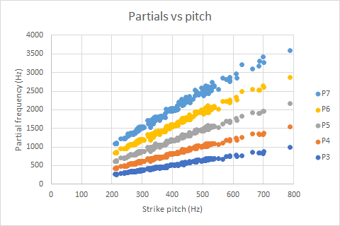
The ratio of each partial frequency to the strike pitch, averaged across 217 tubes, is as follows:
| P2 | P3 | P4 | P5 | P6 | P7 |
|---|---|---|---|---|---|
| 0.65 | 1.25 | 1.99 | 2.86 | 3.81 | 4.86 |
Partials P4, P5, P6 and P7 comprise a harmonic series above the strike pitch with ratios approximately 2 : 3 : 4 : 5 and generate the virtual strike pitch in our ears. Because partials P5 and P6 are flat of the exact harmonic values, the strike pitch will be a little flat of half the P4 frequency. But partial P4 definitely determines the note-name of the tube, that is the note of the strike pitch, and can be used as the nominal frequency for the tube.
Because of the difficulty in identifying partials P1 and P2 in recordings, there is some uncertainty in the identification of the fourth partial. Therefore it is wise to check by listening to recordings before committing to a figure for the strike pitch.
The tubes at Sydney Summer Hill and Lindfield were excluded from the investigation of pitch because their partial frequencies are higher (the tubes are presumably smaller). The mechanism that creates a virtual pitch from partials P4, P5, P6 etc. breaks down for these tubes because of the high frequencies, even though these partials have appropriate ratios. In fact according to my estimates the Sydney Summer Hill tubes pitch by partial P3 alone, and Lindfield (which have even higher partial frequencies) pitch by partial P2 alone. Determining the pitch of these tubes by listening to them was particularly difficult.
The musical effect of tubular bells
With this understanding of the origin of the strike pitch in a tubular bell, other effects we hear can be explained. The intervals in cents from the low partials in a tubular bell to the strike pitch are as follows:
| P2 | P3 | P4 | P5 | P6 |
|---|---|---|---|---|
| -741 | 384 | 1200 | 1831 | 2339 |
| Flat fifth down | Flat major third up | Octave up | Sharp thirteenth | Flat double octave |
The lowest two partials in particular form unusual intervals with the strike note, giving the twangy sound audible in the recordings. Partials P6 and above can be very quiet (and couldn’t be measured in some of the recordings), depending on how hard the tube is struck. Absence of partial P6 and above explains why a strike note is not generated by some of the tubes. It is not possible to control the frequencies of tube partials independently, they are determined by the tubular shape. So it is not possible to create a true-harmonic tubular bell without departing from the uniform shape.
The frequency of partial P4 is double the frequency of the strike pitch, and we can use this partial frequency to investigate the temperament and accuracy of tuning of the seven sets of tubular bells. Here are the average intervals in cents of partial P4 for each tube in a set to the tube with lowest pitch (the tenor or bass tube), given number 1 below:
| Tube | 1 | 2 | 3 | 4 | 5 | 6 | 7 | 8 | 9 | 10 |
|---|---|---|---|---|---|---|---|---|---|---|
| Temperament | 0.0 | 202.9 | 405.9 | 503.1 | 715.2 | 910.7 | 1102.0 | 1198.3 | 1381.9 | 1581.7 |
| No. of tubes | 25 | 24 | 24 | 24 | 24 | 24 | 24 | 23 | 6 | 5 |
| Std. dev. | 0.0 | 17.7 | 14.3 | 15.2 | 14.8 | 18.4 | 27.0 | 15.1 | 32.3 | 20.3 |
The most likely temperament is probably Equal temperament, but the tubes are not closely tuned. Tubes 5 and 6 are on average 15 cents sharp, and tube 9 is on average 20 cents flat. The spread of tuning across the sets is shown by the large standard deviations.
So unfortunately not only are individual tubes a little discordant because of the inharmonic partials, but the tubes are typically not well tuned together as a set.
Tube size and partial frequencies
As explained above, (ref 2) gives a theoretical model for the frequency fn of the nth partial of a tubular bell:
fn = K * ( √(a2 + b2) / L2 ) * (2n + c)p
where K is a constant depending on the elastic properties of the metal, a is the external radius, b is the internal radius, L is the length of the tube, c is a constant, and p is a power to which the 2n + c term is raised. The best fit values for p and c for the tubes investigated here are 1.651 and 0.287.
To further investigate the model, partial frequencies for tubes with known dimensions are needed. I currently have seven sets of data with the required information:
- the 13 bronze tubes from Perth studied in (ref 1)
- the sets of 8 bronze tubes at South Holmwood, Caterham, Parwich and Rownhams
- the 8 iron bars from Effingham (for which b = 0 because they are solid, not tubes)
- the small tubes at Caterham Valley, which are chrome-plated iron.
Re-organising the above equation and taking logs we get:
log( fn / ( √(a2 + b2) * L2 ) = log( K ) + p * log ( 2n + c)
where p and c take the values above. In this equation, K depends solely on the physical properties of the metal, not the dimensions of the tube or the partial number.
A plot of log( fn / ( √(a2 + b2) * L2 ) against log ( 2n + c) for these seven sets of tubes, comprising 769 partials for 61 tubes, is as follows:
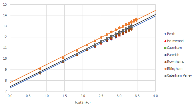
The vertical axis is log( fn / ( √(a2 + b2) * L2 ) . The regression lines are drawn assuming the value of p = 1.651 derived above. The intercept for the three sets of tubes, i.e. log( K ), is different in the three cases because the metal is different. Many of the points for the bronze tubes are so close that they overlay one another.
The theoretical model is a good fit for the data for these tubes with the fitted value of 1.651 for the power of (2n + c).
Analysing a set of tubular bells
Getting the nominal frequencies and note-names for a set of tubular bells is rather easier than for conventional bells. The partials of Harrington tubes are very regular and always have about the same intervals – there are no sharp hums and flat primes to deal with. Note that the partial naming facility in wavanal only works with bells of conventional shape, not tubes. Here is a spectrum of a tubular bell (tube 6 at Mappleborough Green) to illustrate the process. The lowest four partials are marked.
To identify the nominals of a set of tubular bells from recordings:
– Play the sound of the lowest tube and identify its note by comparison with another musical instrument: piano, keyboard, mobile phone app etc. The octave of the note is not material, just its note name.
– Analyse the sound with wavanal and look at the spectrum. You will see partials similar to the above, but partial P1 and possibly P2 may be too quiet to be seen.
– Find partial P4 by looking for a partial with the correct note. It will be one of the bottom 2, 3 or 4 partials. There will only by one partial this low in the spectrum with the correct note. For this tube, I estimate the pitch as F# and the lowest four partials have notes E, A, A and F#.
– The partial with the correct note is the nominal of this tube.
– Alternatively, as I have done, you can estimate the strike pitch frequency with the pitcher program in which case partial P4 will have a frequency double the strike pitch.
– When analysing the remaining tubes, simply pick for the nominals a partial near the bottom of the spectrum that gives an ascending scale.
This procedure has been tested with a considerable number of Harrington tubes and the iron bars at Effingham. Unfortunately it does not give the right answer for the tubes at St Andrew, Sydney and Lindfield. These tubes have such high partial frequencies that the pitch generation mechanism breaks down.
References
- An experimental study of acoustical properties of tubular tower bells, Jie Pan and Sören Bergmann, Proceedings of 20th International Congress on Acoustics, ICA 2010
- The Physics of Musical Instruments, Neville H Fletcher and Thomas D Rossing, 2nd Edition, Springer 1998